
Mit der Komponente "Rippe" können Sie sehr schnell eine beliebige Anzahl an Längsrippen an einem Stabblech definieren. Durch die Vorgabe eines Referenzobjektes lassen sich daran automatisch Schweißnähte vorgeben.
Die Komponente "Rippe" lässt sich auch an kreisförmigen Hohlprofilen anordnen. Dafür wird zusätzlich die Vorgabe der Winkel zwischen den Rippen benötigt.


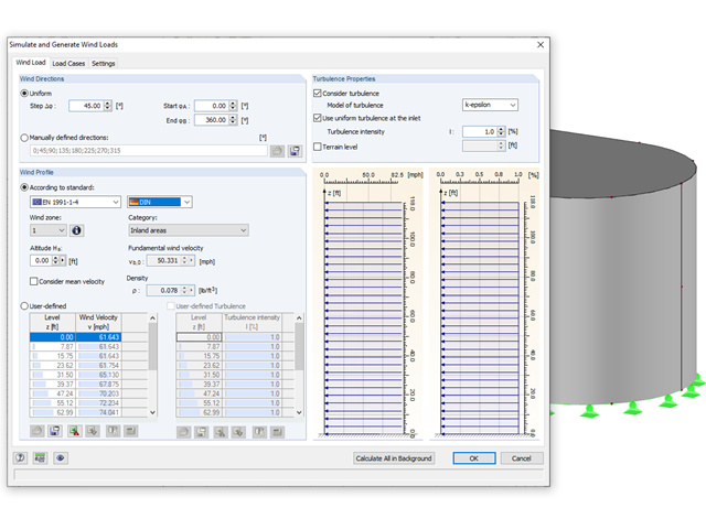
To model structures in RWIND Basic, you find a special application in RFEM and RSTAB. Here, you define the wind directions to be analyzed by means of related angular positions about the vertical model axis. At the same time, you define the elevation-dependent wind profile on the basis of a wind standard. In addition to these specifications, you can use the stored calculation parameters to determine your own load cases for a stationary calculation per each angular position.
As an alternative, you can also use the RWIND Basic program manually, without the interface application in RFEM or RSTAB. In this case, RWIND Basic models the structures and terrain environment directly from the imported VTP, STL, OBJ, and IFC files. You can define the height-dependent wind load and other fluid-mechanical data directly in RWIND Basic.
Discover the new features in RFEM and RSTAB for the determination of wind loads using RWIND:
- Useful load wizards for generating wind load cases with different flow fields in different wind directions
- Wind load cases with freely assignable analysis settings including a user-defined specification of the wind tunnel size and wind profile
- Comprehensive display of the wind tunnel with input wind profile and turbulence intensity profile
- Visualization and use of the RWIND simulation results
- Global definition of a terrain (horizontal planes, inclined plane, table)
Rely on the Dlubal programs even in windy matters. RFEM and RSTAB provide a special interface for exporting models (that is, structures defined by members and surfaces) to RWIND 2. There, the wind directions to be analyzed for your project are defined by means of related angular positions about the vertical model axis. Furthermore, the elevation-dependent wind profile and turbulence intensity profile are defined on the basis of a wind standard. These specifications result in specific load cases, depending on the angle. For this, the fluid parameters, turbulence model properties, and iteration parameters that are all stored globally are helpful. You can extend these load cases by partial editing in the RWIND 2 environment using terrain or environment models from STL vector graphics.
As an alternative, you can also run RWIND 2 manually and without the interface application in RFEM or RSTAB. In this case, the structures and terrain environment in the program are directly modeled by imported STL and VTP files. You can define the height-dependent wind load and other fluid-mechanical data directly in RWIND 2.
Due to its versatile applicability, RWIND 2 is always at your side to support you in your individual projects.
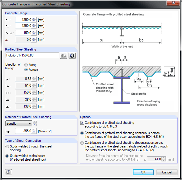
When entering the structural model, you can define single-span and continuous beams with or without cantilevers. Furthermore, it is possible to specify different span lengths with definable boundary conditions (supports, releases) as well as any construction support and moment release in the construction stage. For a complete cross-section, you can create typical composite beam sections on the basis of steel girders (I-sections) with solid concrete flanges, precast plates, trapezoidal sheets, or tapered solid ceilings.
It is also possible to grade cross-sections by means of beam lengths, optionally with concrete encasement. Illustrative figures facilitate the entry of additional transverse reinforcements for trapezoidal sheeting, profile stiffeners, and angled or circular openings in the web. The self-weight is applied automatically when entering loads. In addition, it is possible to consider fixed and variable loads by specifying the concrete age at the beginning of loading for creeping, and to define single, uniform, and trapezoidal loads freely. COMPOSITE-BEAM automatically creates a load combination based on the data of individual load cases.
RF-CONCRETE Surfaces:
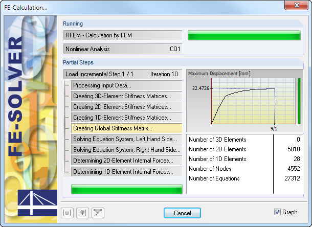
The nonlinear deformation analysis is performed by an iterative process considering the stiffness in cracked and non-cracked sections. The nonlinear reinforced concrete modeling requires definition of material properties varying across the surface thickness. Therefore, a finite element is divided into a certain number of steel and concrete layers in order to determine the cross-section depth.
The mean steel strengths used in the calculation are based on the 'Probabilistic Model Code' published by the JCSS technical committee. It is up to the user whether the steel strength is applied up to the ultimate tensile strength (increasing branch in the plastic area). Regarding material properties, it is possible to control the stress-strain diagram of the compressive and tensile strength. For the concrete compressive strength, you can select a parabolic or a parabolic-rectangular stress-strain diagram. On the tension side of the concrete, it is possible to deactivate the tensile strength as well as to apply a linear-elastic diagram, a diagram according to the CEB-FIB model code 90:1993, and concrete residual tensile strength considering the tension stiffening between the cracks.
Furthermore, you can specify which result values should be displayed after the nonlinear calculation at the serviceability limit state:
- Deformations (global, local based on non-/deformed system)
- Crack widths, depths, and spacing of the top and bottom sides in principal directions I and II
- Stresses of the concrete (stress and strain in principal direction I and II) and of the reinforcement (strain, area, profile, cover, and direction in each reinforcement direction)
RF-CONCRETE Members:
The nonlinear deformation analysis of beam structures is performed by an iterative process considering the stiffness in cracked and non-cracked sections. The material properties of concrete and reinforcing steel used in the nonlinear calculation are selected according to a limit state. The contribution of the concrete tensile strength between the cracks (tension stiffening) can be applied either by means of a modified stress-strain diagram of the reinforcing steel, or by applying a residual concrete tensile strength.